Projects
Robotic System for Visual Inspection and Defect Classification: Sandia National Laboratories
As part of a senior design project sponsored by Sandia National Laboratories, my team developed a compact, automated part inspection system to improve the efficiency and accuracy of visual defect detection in manufactured components. The system uses a precise electromechanical platform capable of five degrees of freedom for multi-axis manipulation of parts within a constrained 6x6x6 inch volume. It integrates stepper and servo motors with lead screw–driven linear rails for smooth, reliable motion, paired with a user-friendly GUI and an iOS app for image capture. An unsupervised machine learning pipeline, powered by Amazon’s PatchCore algorithm, enables accurate defect detection without requiring large datasets. The software developed for the project is available in the team’s GitHub repository.
Throughout the project, we iterated on mechanical and software subsystems to ensure robust performance, using Finite Element Analysis to validate structural components and extensive testing to confirm reliability. The system successfully inspected components with varying geometries and met Sandia’s specifications for accuracy, weight, and footprint. The result is a cost-effective, scalable solution that enhances the repeatability and objectivity of visual inspection in advanced manufacturing environments.


Automated Plant Care System: Design Methodology ME366J Project
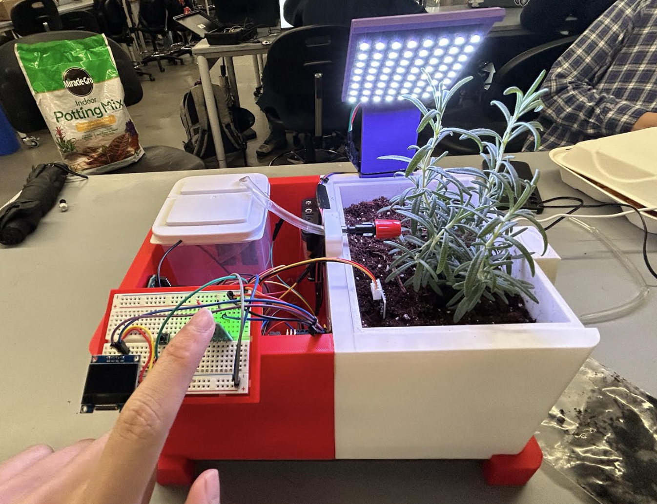
As part of my Design Methodology course at The University of Texas, my team and I set out to create an automated plant care system. The objectives were to develop a user-friendly, cost-effective, and aesthetically pleasing product that could simplify plant maintenance for busy individuals. We began by conducting a thorough customer needs analysis, gathering insights from potential users to understand their pain points and priorities—such as low maintenance, compact design, and visual integration into home environments. Using this input, we developed a functional model to map the system's key operations, including water delivery, lighting, and sensor feedback, which guided our design decisions.
Through several design iterations, we refined both the form and function of the system, using CAD modeling and physical prototyping. We conducted FMEA to identify potential failure points and ran FEA to verify structural robustness of critical components. A key feature of the final design was a built-in drainage system and a plant container housed in a sliding drawer mechanism, allowing users to easily change soil or swap out plants without disrupting the rest of the system. The system was powered by an Arduino microcontroller, which enabled real-time feedback and automated responses based on light and soil moisture sensors. This integration allowed the system to adjust watering and lighting conditions dynamically, providing a reliable and self-sustaining solution for indoor plant care.


Longhorn Racing Formula SAE: Bellcrank System
Being a part of UT Austin’s Formula SAE team, Longhorn Racing, gave me the opportunity to advance my skills outside the classroom. As a Vehicle Dynamics Engineer, I was responsible for the bellcrank system for our 2023 racecar, an essential component of our suspension system. The bellcrank plays a central role, as it connects to a number of critical components and allows us to set up the suspension according to our motion ratio. In the rear, the bellcranks were connected to the chassis, shocks, and push rods, while in the front, they played the same role, in addition to connecting to the anti-roll bar.
Starting off with a one-piece bellcrank concept, and then moving towards having two faces, which are easier to manufacture and weigh less, I made multiple iterations through the use of FEA and topology optimization. Finally, Fusion 360 CAM was used to manufacture the parts using a CNC.

With my knowledge initially limited on how a bellcrank works, I made initial sketches and designs based off previous designs. Later, I found that using a two-face concept would result in greater weight saving, and it would be easier to manufacture.

This project enabled me to develop my simulation skills. The image above is an example of one of the earlier topology optimizations, which I used to reduce as much material as possible. Setting up these simulations required understanding the various load cases the system would face, considering the multiple forces and their respective angles at maximum droop and heave.


Changes had to be made late on in the process as I realized that the team needed to have flexibility in setting up the anti-roll bar (ARB). This meant that I needed to add more mounting points to the front bellcranks, where the ARB would connect. This required going back and redoing the topology optimization, taking into account the two extremes of placing the anti-roll bar at the far left or far right mounting points we had designated. Once this was complete, I moved on to the final step of the process, selecting the bearings and finishing the designs of the mounting points. Finally, using Fusion 360 CAM, the bellcranks were manufactured using a Haas CNC in-house at UT Austin's Mechanical Engineering Machine Shop.
Remote-Control Racecar: Machine Elements ME338 Design Project
For the final project in my Machine Elements class, I, along with a team of fellow students set out to create a remote-control car. This project was interesting as it emphasized the importance of organizing a team, working with others, and using basic components and a limited budget to create a final product. The project can be divided into 3 systems: chassis, drivetrain, and steering. My main responsibility was for the chassis. The initial design was complicated, but after going through an iterative process, I came up with a concept that prioritized simplicity, ease of manufacturing and assembly, and weight saving, while also maintaining structural integrity.


The project culminated in a race with other teams to celebrate the end of the semester where unfortunately, the gears in the servo motor (which controlled our steering system) got stripped, which meant that we couldn’t secure a placement. Nevertheless, the experience was invaluable as we got to implement the theoretical knowledge we had gained in the classroom to create a physical product.
Selected Designs from Longhorn Racing


The first part I created for the Longhorn Racing team was a back-nut as part of the rear wheel assembly. The purpose of the back nut is to apply a preload to the bearings. This is crucial, as by applying an axial force, we can eliminate clearance and prevent plastic deformation. My biggest takeaway in designing this component was the realization that when designing anything, one must understand that there are limits that may come further down the line that need to be accounted for. In this specific case, I needed to take a design for assembly approach, as I realized that the team did not possess a wrench of the required size. To accommodate for this, I changed the design to one that would allow for the use of a u-shaped spanner, which the team had available.

As an engineer, you always want to innovate upon previous designs, keeping in mind that you not only want to improve the performance of your product, but you may want to simply make it easier for users to interact with. Reflecting upon the Formula SAE Michigan 2022, one change I proposed was to allow for our tie-rods to be adjusted easily. By using a double-adjuster bolt, team-members could now adjust the tie-rods with a simple manoeuvre, rather than having to remove and reassemble major components to make the change.

As the team transitioned to a new set of OZ-magnesium 10” wheels, a new set of center lock nuts needed to be created. This part was made with 4130 steel.
